As the need for higher data rates increases, industry often looks for new ways to increase the utilization of limited spectrum available by adding complexities to other areas like antennas, more baseband power etc. Even though MIMO concepts are not new, this has been in focus to meet the user demands. Here, one attempt is to increase the number of Tx and Rx antennas (aka MIMO) by achieving the various diversity gains.
In 3GPP release 12, up to 8 Tx antenna ports, arranged horizontally, supported in DL-MIMO.
Full Dimensional - MIMO (FD-MIMO) is in 3GPP since release 13 towards LTE-Advanced feature. One can place the antennas linearly or in 2 Dimensional active array form. Depends on the need, one can decide to selectively enable/disable these antennas which makes 3D beam-forming by controlling the vertical elevation) and horizontal (azimuth) of the antenna array system. Since 4x4 MIMO systems are already available in LTE legacy, one can think of 8x8 or 4x16 or 2x32 active antenna array systems depends on the space available to place this array at the top of base station.
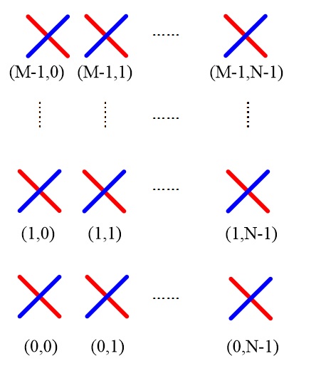
Fig: From 3GPP TR 36.897, Antenna array model represented by (M, N, P)
M- No of antennas in vertical (1,2,4...)
N- No of antennas in horizontal (1,2,4...)
P- Antenna Polarization (P=2 for cross polarization and 1 for Co-polarization)
As you doubt, how would UE will know what kind of antenna pattern that base stations are using? Like in earlier LTE legacy concepts, here also planned to inform the UE first via System info, pilot channel transmission and later get the feedback (in the form of CSI reports etc) from UE to understand in which direction the reception quality is better and ways to improve it. It is essentially done by switching the antennas based on the feedback feedback from UE.
CRS, CSI-RS, DM-RS, ... continues to beam-formed CSI-RS in FD-MIMO:
Traditionally CRS and CSI-RS are sent by the eNBs so that UE can measure the channel and feedback the CSI feedback info (PMI, RI and CQI). For TDD case, SRS based (Sounding RS from the UE to base station) method is used to estimate the CSI at the base station itself. Since these are common to all UEs in Idle and un-precoded, DM-RS was introduced for those in connected to the base station (data call).
For FD-MIMO, beam-formed CSI-RS is introduced where UE selects the best weight and feedback its index to the eNB. This method seems having more advantages in terms of less uplink feedback overhead, less downlink pilot overhead, higher quality in RS. For more details, please read "Overview of Full-Dimension MIMO in LTE-Advanced Pro" and also refer 3GPP TR 36.897 Study on elevation beamforming / Full-Dimension (FD) Multiple Input Multiple Output (MIMO) for LTE (Release 13).
In release 13, FD-MIMO was introduced with TM 9 and TM 10 configurations and UE indicates its capability per-TM sub-features and optionally it can send per-BoBC (Band of a bandcombo) basis.
Per-TM capabilities are transferred by RRC via PhyLayerParameters-v1320 and it may be part of UE-EUTRA-Capability-v1320-IEs and UE-EUTRA-CapabilityAddXDD-Mode-v1320
Per-BoBC capabilities are indicated by RRC via BandCombinationParameters-v1320 and it may be part of RF-Parameters-v1320, via SupportedBandCombination-v1320, SupportedBandCombinationAdd-v1320, or SupportedBandCombinationReduced-v1320
Some of the sub-features are below:
1. Class A CSI reporting: It comes with
a) increased number of CSI-RS ports from minimum of 8 to 16 which increases the maximum precoding matrix size. For 12 ports, 3 CSI-RS configs for 4 ports are selected. Similarly, for 16 ports, 2 CSI-RS configs for 8 ports are selected.
b) 2D code book and
c) 3 pre-coding matrix indicators (i1,1), (i1,2) and i2 (against 2 in legacy i1 and i2)
Here (i1,1), (i1,2) represents a grid of beam directions in first and second dimension and i2 represents selection of beams at a beam grid and phase of beams. In this method, non-precoded CSIRSs are sent by the base station and the UE derives the precoder.
Here, CSI-RS overhead increases in proportion to the number of antenna ports.
Here, CSI-RS overhead increases in proportion to the number of antenna ports.
2. Class B CSI reporting: To reduce the CSI-RS overhead, beam formed CSI-RS introduced. Here, CSI-RS beams are denoted by NB. If NB=1, CSI info PMI/RI/CQI are reported back however with UE specific beam formed CSI-RS reduces the overload. If NB>1, base station transmits multiple CSI-RS with different beams. UE measures the suitable one and reports back the CSI Resource Index (CRI) along with the PMI/RI/CQI. 3GPP release 13 supports up to 8 NB. This seems to be promising method for 5G systems and operators opr vendors might prefer this one.
3. CSI-RS in DwPTS: In this, CSI-RS allowed to transmit in DwPTS for Special Subframe config 1,2,3,4,6,7 or 8 for normal cyclic prefix and Special Subframe config 1,2,3,5 or 6 for extended cyclic prefix.
4. DMRS improvements: It introduces OCC (Orthogonal cover code). It supports of MU-MIMO with antenna ports 7,8,11,13 with OCC length of 4.
5. SRS improvements: With more number of UEs transmitting SRS in UL, Channel estimation info becomes worse, also added interference due to the UEs in the neighboring cells. In Rel-13, this is overcome either by extending the SRS bits, precoded SRS, 4Tx antenna switching for SRS transmission, transmitting SRS on unused PUSCH DMRS resources, transmitting SRS on PUSCH resources.
In my next blog, I will give more details on this feature in 5G NR perspective and how it will be developed.


Nice Explained. It would also be interesting for you to know about Miot Wireless Solutions which provides one stop solutions and best-in-class compact, high-gain 3G, 4G/LTE and 5G Cellular and Wi-Fi Antennas for connected smart devices and today’s high-performance LTE networks. For more details please visit www.miotsolutions.com
ReplyDeleteThe customized RF solution stands for Radio Frequency solution. It is an electronic device very small in size which is used to transmit and receive the radio signals for the purpose of communication between two devices. Miot wireless solutions are a leading customized RF solution manufacture company. We readily integrate a variety of functions for you into custom designed modules, subsystems, bench top devices, or rack units, and deliver them as turnkey testing solutions.
ReplyDelete